1. G80 Motion Stop
G80 turns off all motion. You should think of it as the off position on a rotary switch where the other positions are the different possible motion modes. In the EMC interpreter, G80 is one of the modal codes so any other code will replace it. The result of the following lines of code is the same.
G90 G81 X1 Y1 Z1.5 R2.8 (absolute distance canned cycle)
G80 (turn off canned cycle motion)
G0 X0 Y0 Z0 (turn on rapid traverse and move to coordinate home)
produces the same final position and machine state as
G90 G81 X1 Y1 Z1.5 R2.8 (absolute distance canned cycle)
G0 X0 Y0 Z0 (turn on rapid traverse and move to coordinate home)
The advantage of the first set is that, the G80 line clearly turns off the G81 canned cycle. With the first set of blocks, the programmer must turn motion back on with G0, as is done in the next line, or any other motion mode G word.
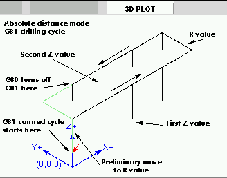
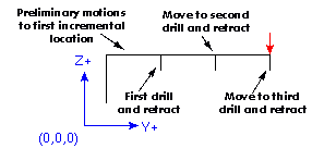
If a canned cycle is not turned off with G80 or another motion word, the canned cycle will attempt to repeat itself using the next block of code that contains an X, Y, or Z word. The following file drills (G81) a set of eight holes as shown in the following caption.
N100 G90 G0 X0 Y0 Z0 (coordinate home)
N110 G1 X0 G4 P0.1
N120 G81 X1 Y0 Z0 R1 (canned drill cycle)
N130 X2
N140 X3
N150 X4
N160 Y1 Z0.5
N170 X3
N180 X2
N190 X1
N200 G80 (turn off canned cycle)
N210 G0 X0 (rapid home moves)
N220 Y0
N230 Z0
N240 M2 (program end)
|
Note
|
Notice the z position change after the first four holes. Also, this is one of the few places where line numbers have some value, being able to point a reader to a specific line of code. |
The use of G80 in line N200 is optional because the G0 on the next line will turn off the G81 cycle. But using the G80. as example 1 shows, will provide for an easily readable canned cycle. Without it, it is not so obvious that all of the blocks between N120 and N200 belong to the canned cycle.
If you use G80 and do not set another modal motion code soon after, you may get one of the following error messages.
Cannot use axis commands with G80

Coordinate setting given with G80
These should serve as a reminder that you need to write in a new motion word.
2. G81 Drilling
The G81 cycle is intended for drilling.
The cycle functions as follows:
-
Preliminary motion to start position.
-
Move the Z-axis only at the current feed rate to the Z position.
-
Retract the Z-axis at traverse rate to clear Z. This cycle was used in the description of G80 above but is explained in detail here.
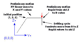
Suppose the current position is (X1, Y2, Z3) and the following line of NC code is interpreted.
G90 G98 G81 X4 Y5 Z1.5 R2.8
This calls for absolute distance mode (G90) and OLD_Z retract mode (G98) and calls for the G81 drilling cycle to be performed once.
The X value and X position are 4.
The Y value and Y position are 5.
The Z value and Z position are 1.5.
The R value and clear Z are 2.8. OLD_Z is 3.
The following moves take place:
-
a traverse parallel to the XY plane to (X4, Y5, Z3)
-
a traverse parallel to the Z-axis to (X4, Y5, Z2.8).
-
a feed parallel to the Z-axis to (X4, Y5, Z1.5)
-
a traverse parallel to the Z-axis to (X4, Y5, Z3)
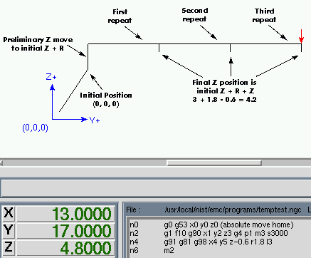
Suppose the current position is (X1, Y2, Z3) and the following line of NC code is interpreted.
G91 G98 G81 X4 Y5 Z-0.6 R1.8 L3
This calls for incremental distance mode (G91) and OLD_Z retract mode (G98). It also calls for the G81 drilling cycle to be repeated three times. The X value is 4, the Y value is 5, the Z value is -0.6 and the R value is 1.8. The initial X position is 5 (=1+4), the initial Y position is 7 (=2+5), the clear Z position is 4.8 (=1.8+3), and the Z position is 4.2 (=4.8-0.6). OLD_Z is 3.
The first preliminary move is a traverse along the Z axis to (X1,Y2,Z4.8), since OLD_Z < clear Z.
The first repeat consists of 3 moves.
-
a traverse parallel to the XY-plane to (X5, Y7, Z4.8)
-
a feed parallel to the Z-axis to (X5, Y7, Z4.2)
-
a traverse parallel to the Z-axis to (X5, Y7, Z4.8)
The second repeat consists of 3 moves. The X position is reset to 9 (=5+4) and the Y position to 12 (=7+5).
-
a traverse parallel to the XY-plane to (X9, Y12, Z4.8)
-
a feed parallel to the Z-axis to (X9, Y12, Z4.2)
-
a traverse parallel to the Z-axis to (X9, Y12, Z4.8)
The third repeat consists of 3 moves. The X position is reset to 13 (=9+4) and the Y position to 17 (=12+5).
-
a traverse parallel to the XY-plane to (X13, Y17, Z4.8)
-
a feed parallel to the Z-axis to (X13, Y17, Z4.2)
-
a traverse parallel to the Z-axis to (X13, Y17, Z4.8)
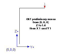
Now suppose that you execute the first G81 block of code but from (X0, Y0, Z0) rather than from (X1, Y2, Z3).
G90 G98 G81 X4 Y5 Z1.5 R2.8
Since OLD_Z is below the R value, it adds nothing for the motion but since the initial value of Z is less than the value specified in R, there will be an initial Z move during the preliminary moves.
This is a plot of the path of motion for the second g81 block of code.
G91 G98 G81 X4 Y5 Z-0.6 R1.8 L3
Since this plot starts with (X0, Y0, Z0), the interpreter adds the initial Z0 and R1.8 and rapids to that location. After that initial Z move, the repeat feature works the same as it did in example 3 with the final Z depth being 0.6 below the R value.
G90 G98 G81 X4 Y5 Z-0.6 R1.8
Since this plot starts with (X0, Y0, Z0), the interpreter adds the initial Z0 and R1.8 and rapids to that location as in Example 4. After that initial Z move, the rapid traverse move to X4 Y5 is done. Then the final Z depth being 0.6 below the R value. The repeat function would make the Z move in the same location again.
3. G82 Drilling, Dwell
The G82 cycle is intended for drilling.
-
Preliminary motion to start position.
-
Move the Z-axis only at the current feed rate to the Z position.
-
Dwell for the given number of seconds.
-
Retract the Z-axis at traverse rate to clear Z. The motion of a G82 canned cycle looks just like G81 with the addition of a dwell at the bottom of the Z move. The length of the dwell is specified by a P- word in the G82 block.
G90 G82 G98 X4 Y5 Z1.5 R2.8 P2
Would be equivalent to Example 2 above with a dwell added at the bottom of the hole.
4. G83 Deep Drilling
The G83 cycle is intended for deep drilling or milling with chip breaking. This cycle takes a Q value which represents a delta increment along the Z-axis. Machinists often refer to this as peck drilling.
-
Preliminary motion to start position.
-
Move the Z-axis only at the current feed rate downward by delta or to the Z position, whichever is less deep.
-
Dwell for 0.25 second.
-
Retract at traverse rate to clear Z
-
Repeat steps 1 - 3 until the Z position is reached.
-
Retract the Z-axis at traverse rate to clear Z.
G83 functions the same as G81 with the addition of peck drilling.
5. G84 Tapping
The G84 cycle is intended for right-hand tapping.
-
Preliminary motion to start position.
-
Start speed-feed synchronization.
-
Move the Z-axis only at the current feed rate to the Z position.
-
Stop the spindle.
-
Start the spindle counterclockwise.
-
Retract the Z-axis at the current feed rate to clear Z.
-
If speed-feed synch was not on before the cycle started, stop it.
-
Stop the spindle.
-
Start the spindle clockwise.
6. G85 Boring
The G85 cycle is intended for boring or reaming.
-
Preliminary motion to start position.
-
Move the Z-axis only at the current feed rate to the Z position.
-
Retract the Z-axis at the current feed rate to clear Z. This motion is very similar to g81 except that the tool is retracted from the hole at feed rate rather than rapid.
7. G86 Boring, Rapid Out
The G86 cycle is intended for boring.
-
Preliminary motion to start position.
-
Move the Z-axis only at the current feed rate to the Z position.
-
Dwell for the given number of seconds.
-
Stop the spindle turning.
-
Retract the Z-axis at traverse rate to clear Z.
-
Restart the spindle in the direction it was going. This cycle is very similar to g82 except that it stops the spindle before it retracts the tool and restarts the spindle when it reaches the clearance value R.
8. G87 Back Boring
The G87 cycle is intended for back boring.
The situation is that you have a through hole and you want to counter bore the bottom of hole. To do this you put an L-shaped tool in the spindle with a cutting surface on the UPPER side of its base. You stick it carefully through the hole when it is not spinning and is oriented so it fits through the hole, then you move it so the stem of the L is on the axis of the hole, start the spindle, and feed the tool upward to make the counter bore. Then you stop the tool, get it out of the hole, and restart it.
This cycle uses I and J values to indicate the position for inserting and removing the tool. I and J will always be increments from the X position and the Y position, regardless of the distance mode setting. This cycle also uses a K value to specify the position along the Z-axis of the top of counterbore. The K value is an absolute Z-value in absolute distance mode, and an increment (from the Z position) in incremental distance mode.
-
Preliminary motion to start position.
-
Move at traverse rate parallel to the XY-plane to the point indicated by I and J.
-
Stop the spindle in a specific orientation.
-
Move the Z-axis only at traverse rate downward to the Z position.
-
Move at traverse rate parallel to the XY-plane to the X,Y location.
-
Start the spindle in the direction it was going before.
-
Move the Z-axis only at the given feed rate upward to the position indicated by K.
-
Move the Z-axis only at the given feed rate back down to the Z position.
-
Stop the spindle in the same orientation as before.
-
Move at traverse rate parallel to the XY-plane to the point indicated by I and J.
-
Move the Z-axis only at traverse rate to the clear Z.
-
Move at traverse rate parallel to the XY-plane to the specified X,Y location.
-
Restart the spindle in the direction it was going before.
Example 6 uses a incremental distances from (X0, Y0, Z0) so the preliminary moves look much like those in Example 5 but they are done using the G87 backbore canned cycle.
G91 G87 M3 S1000 X1 Y1 Z-0.4 R1.4 I-0.1 J-0.1 K-0.1
Now the G87 canned cycle turns the spindle on and moves back up into the bore at the programmed feed rate. This is the real cutting action of this canned cycle. With the proper tool in a boring bar this cycle will produce a chamfer on the bottom side of the bore. G87 can also be used to produce a larger diameter bore on the bottom side of the bore.
This canned cycle assumes spindle orientation which has not been implemented in the EMC to date. The proper alignment of the tool tip to the oriented spindle is critical to the successful insertion of the tool through the hole to be backbored.
9. G88 Boring with Stop
The G88 cycle is intended for boring. This cycle uses a P value, where P specifies the number of seconds to dwell.
-
Preliminary motion to start position.
-
Move the Z-axis only at the current feed rate to the Z position.
-
Dwell for the given number of seconds.
-
Stop the spindle turning.
-
Stop the program so the operator can retract the spindle manually.
-
Restart the spindle in the direction it was going. It is unclear how the operator is to manually move the tool because a change to manual mode resets the program to the top. We will attempt to clarify that step in this procedure.
10. G89 Boring Feed Out
The G89 cycle is intended for boring. This cycle uses a P value, where P specifies the number of seconds to dwell.
-
Preliminary motion to start position.
-
Move the Z-axis only at the current feed rate to the Z position.
-
Dwell for the given number of seconds.
-
Retract the Z-axis at the current feed rate to clear Z. This cycle is like G82 except that the tool is drawn back at feed rate rather than rapid.
11. G98 Retract to Origin
Program a G98 and the canned cycle will use the Z position prior to the canned cycle as the Z return position if it is higher than the R value specified in the cycle. If it is lower then the R value will be used. The R word has different meanings in absolute distance mode and incremental distance mode.
G0 X1 Y2 Z3
G90 G98 G81 X4 Y5 Z-0.6 R1.8 F10
The G98 to the second line above means that the return move will be to the value of Z in the first line since it is higher that the R value specified.
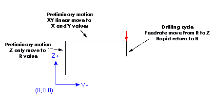
12. G99 Retract
Program a G99 and the canned cycle will use the R value as the Z return position.
13. G91 with G98-99
Neither G98 or G99 will have any affect when in incremental distance mode (G91) and a positive R value is specified because the R value is added to OLD_Z and that result is used as the initial level for a G98. The same value is the computed R value so G99 will also return to the same place. When the value of R is less than OLD_Z and incremental distance mode is turned on, G99 will retract the tool to OLD_Z plus the negative R value. The return will be below OLD_Z.
14. Why use a canned cycle?
There are at least two reasons for using canned cycles. The first is the economy of code. A single bore would take several lines of code to execute.
Example 1 above demonstrated how a canned cycle could be used to produce 8 holes with ten lines of nc code within the canned cycle mode. The program below will produce the same set of 8 holes using five lines for the canned cycle. It does not follow exactly the same path nor does it drill in the same order as the earlier example. But the program writing economy of a good canned cycle should be obvious.
G90 G0 X0 Y0 Z0 (move coordinate home)
G1 F10 X0 G4 P0.1
G91 G81 X1 Y0 Z-1 R1 L4(canned drill cycle)
G90 G0 X0 Y1
Z0
G91 G81 X1 Y0 Z-0.5 R1 L4(canned drill cycle)
G80 (turn off canned cycle)
M2 (program end)
The G98 to the second line above means that the return move will be to the value of Z in the first line since it is higher that the R value specified.
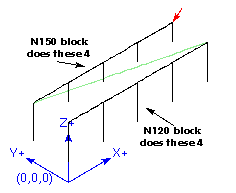
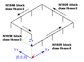
This example demonstrates the use of the L word to repeat a set of incremental drill cycles for successive blocks of code within the same G81 motion mode. Here we produce 12 holes using five lines of code in the canned motion mode.
G90 G0 X0 Y0 Z0 (move coordinate home)
G1 F50 X0 G4 P0.1
G91 G81 X1 Y0 Z-0.5 R1 L4 (canned drill cycle)
X0 Y1 R0 L3 (repeat)
X-1 Y0 L3 (repeat)
X0 Y-1 L2 (repeat)
G80 (turn off canned cycle)
G90 G0 X0 (rapid home)
Y0
Z0
M2 (program end)
The second reason to use a canned cycle is that they all produce preliminary moves and returns that you can anticipate and control regardless of the start point of the canned cycle.